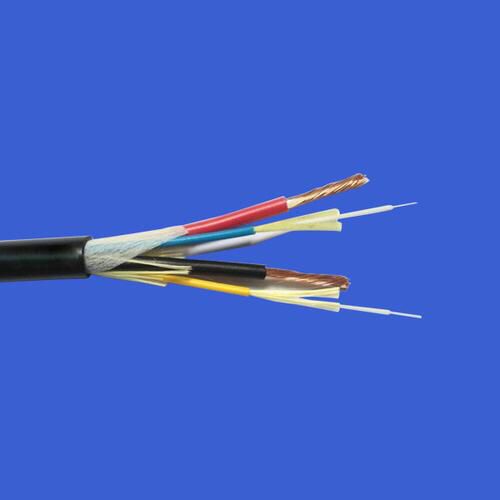
In AI computing data centers and high-density cabling environments of large-scale data centers, MPO (Multi-fiber Push On) multi-fiber push-pull fiber optic patch cords are the core solution for replacing dozens of LC single-fiber patch cords. A single MPO can integrate 4 to 144 fibers, significantly reducing cable clutter in racks and improving deployment efficiency. This article provides a comprehensive breakdown from fundamental parameters, common fiber counts, compatible optical modules, polarity, and gendered connectors, helping engineers avoid pitfalls during product selection.
MPO Patch Cord Basic Core Parameter Concept: Number of Fibers – Determines the Upper Limit of Parallel Transmission Channels
MPO connectors rely on MT ferrules to carry multiple optical fibers. Industry-standard fiber counts include 4/8/12/16/24/48/72/144, categorized into single-row configurations (4/8/12/16 fibers) and dual-row configurations (24/48 fibers and above). The number of fibers directly corresponds to the number of transmit and receive channels in optical modules, making it the primary criterion for selection.
Male / Female (PIN pin distinction)
Male MPO: Plug with 2 metal PIN pins; all SR4/SR8 parallel optical module ports are male.
Female MPO: Plug with pin receptacle; patch cords, MPO distribution boxes, and branch cables are female connectors.
Hard rule: Only male-to-female connections are allowed; forced insertion or removal of male-to-male or female-to-female connectors will damage the pins, resulting in immediate failure and scrapping of the optical module interface and patch cord.


Three polarities Type A/B/C (ensures Tx/Rx signal compatibility)
Signal transmission requires that the transmitting (Tx) end must be connected to the receiving (Rx) end at the other end, with polarity control determining the fiber core arrangement. The TIA-568 industry standard is divided into three categories:
1. Type A (Straight-through): Keys at both ends face opposite directions, with fiber sequences directly corresponding (1↔1, 2↔2, ..., 12↔12), commonly used for patching within distribution boxes.
2. Type B (cross type, most commonly used in data centers): The keys on both ends are aligned in the same direction, with fiber sequence completely reversed (1↔12, 2↔11, ..., 12↔1). Type B is the default choice for direct connections between switches and servers, as well as for interconnecting optical modules.
3. Type C (paired cross type): Each pair of fibers is swapped within a group of two (1↔2, 3↔4), commonly used in MPO-to-LC branch connections and high-density patching cabinets.

4. End-face grinding (multi-mode / single-mode distinction)
UPC flat polishing: compatible with OM3/OM4/OM5 multimode MPO patch cords, low reflection loss, standard with 850nm VCSEL optical modules.
APC 8° bevel grinding: Specifically designed for OS2 single-mode MPO, eliminating long-distance single-mode reflection interference; 1310/1550 nm single-mode 400G/800G DR4/DR8 optical modules must use APC end faces.

5. Fiber Type Matching
MPO patch cords are available in multimode (OM1/OM2/OM3/OM4/OM5) and single-mode OS2:
Short-range TOR interconnect for AI data centers: 850nm multimode MPO (OM4/OM5);
Campus backbone and long-haul data center interconnect: 1310nm single-mode OS2 MPO.
Mainstream MPO fiber count specifications, data rates, and complete correspondence with optical modules
1. 4-core MPO (niche inventory item)
Structure: Single row, 4-core;
Applicable to: legacy 40G single-channel short-reach links, 5G base station fronthaul;
Matching module: Early low-speed 40G QSFP+ simplified version, now largely phased out in current AI computing data centers.
2. 8-core MPO
Channel logic: 4 receive and 4 transmit, fully supporting 4 pairs of bidirectional optical channels;
Compatible optical modules: 40G QSFP+ SR4, 100G QSFP28 simplified version, 50G SFP56 parallel module;
Scenario: Small to medium-sized IDCs, 40G traditional data center upgrades; AI new clusters are rarely used independently.
3. 12-core MPO (mainstream standard for traditional data centers)

Channel logic: Use the middle 8 cores for 4 receive and 4 transmit transmission, with the remaining 4 cores reserved as redundant backup.
Compatible optical module:
100G QSFP28 SR4 (multimode 850nm, the mainstream option for existing AI data center infrastructure)
200G SR4, 400G DR4 single-mode parallel modules;
Suitable for: 100G server TOR switch interconnection, medium and small-scale computing clusters—offering the best cost-performance ratio, ideal for upgrading existing data centers.

4. 16-core MPO (800G/1.6T AI Computing Power New Standard)

Channel logic: Full 8 receive and 8 transmit bidirectional channels, with no idle redundancy;
Compatible optical modules (mainstream for AI clusters):
800G OSFP/QSFP-DD SR8, DR8;
1.6T SR8.2 Next-generation ultra-high-speed optical module;
Applicable scenarios: new AI high-performance computing data centers, GB200 GPU clusters with NVLink interconnect, 800G/1.6T leaf-and-spine architecture switches—standard configuration for newly built computing centers in 2026.
|
Optical module data rate |
Mainstream models |
Standard MPO fiber count |
Fiber optic types |
Typical transmission distance |
|
100G |
QSFP28 SR4 |
12-core (using 8-core) |
OM4/OM5 Multimode |
100m/150m |
|
400G |
QSFP-DD SR8 |
16-core |
OM4/OM5 Multimode |
100m/150m |
|
400G |
QSFP-DD DR4 |
12-core |
OS2 Single Mode |
500m |
|
800G |
OSFP SR8 |
16-core |
OM4/OM5 Multimode |
70m (OM4) / 100m (OM5) |
|
800G |
QSFP-DD DR8 |
16-core |
OS2 Single Mode |
500m |
|
800G |
QSFP-DD800 DR8+ |
16-core |
OS2 Single Mode |
2km |
Key Points to Avoid Pitfalls in Product Selection
1. Prioritize fiber count matching for optical module channels: 800G/1.6T parallel optical modules must use 16-fiber MPO; 12-fiber cannot fully support 8 channels, and forcing its use will halve bandwidth and cause packet loss.
2. Male and female connectors must not be mixed up. Since the optical module port is a male PIN, the straight-through patch cable on both ends must be female MPO; when using adapter boxes, ensure proper matching of male and female connectors.
3. For computing data centers, uniformly select Type B polarity; all direct links from switches to servers shall use Type B crossover cables to prevent link failure caused by reversed Tx/Rx connections.
4. Multimode and single-mode end faces must not be mixed. Using a multimode UPC patch cord with a single-mode APC optical module will result in significant reflection loss and frequent bit errors in high-speed links.
5. AI new clusters prioritize 16-fiber MPO; future 1.6T/3.2T optical modules are based on a 16-fiber, 8-channel architecture, enabling direct deployment of 16-fiber cabling in newly built data centers to avoid re-cabling later.
The core selection logic for MPO patch cords is that the number of fibers is determined by the optical module data rate, fiber type by transmission distance, and connector polarity (male/female) by the mating equipment. In traditional 100G data centers, 12-fiber MPO remains dominant, whereas in newly built AI computing clusters, high-speed interconnects such as 800G and 1.6T have fully transitioned to 16-fiber MPO solutions. Fiber counts of 24 or more are used exclusively for high-density backbone aggregation within data centers and do not directly connect to server optical ports. Clarifying the fiber count mapping not only reduces cabling costs but also ensures long-term stable scalability of AI computing networks.