DFT TELECOM
DFT24Vdc/110Vdc-30DS DC-DC Converter
DFT24Vdc/110Vdc-30DS DC-DC Converter
Couldn't load pickup availability
Product Introduction
AC/DC-DC Converter is specially designed for meeting the requirements of all kinds of communication equipment of communication and electric power departments.
AC/DC-DC Converter adopts the high frequency switching technology and hDS many good points, including high accuracy voltage stabilizing, low output noise, strong capacity of resisting disturbance, small volume, light weight, beautiful external shape, etc.
AC/DC-DC Converter is the ideal configuration supplying power to the communication equipments of different voltage grades
Main Characteristics
1. Input and output complete isolation, safety and credibility.
2. Advance current control mode and stable & reliable circuit topological structure.
3. The key parts all adopt the imported components, and main technical indexes are much higher than the national related standards
4. All-around protection functions, output over/under voltage, over current, short-circuit and over temperature protection of whole body
5. Adopt no-mDSter automatic equalized current technology, can parallel connection, convenient to extend the capacity
6. AC and DC input are available, and AC and DC can be fully isolated by electricity
Model definition
BVT24Vdc/110Vdc-30DS
Model:BVT- [ VV ] / [ vvaa ]
. BVT----- BRAND
.VV- ----Rated DC input voltage/-Rated AC input voltage
.-Conversion;
.vv- ----Rated DC Output Voltage,aa -----Rated DC Output Current/Power;
Structure of DC Converter

Specification
|
Model |
BVT24Vdc/110Vdc-30DS |
|
DC Input rate voltage |
24Vdc |
|
DC Input voltage range |
20~30Vdc |
|
Output rate voltage |
110VDC |
|
Output voltage range |
90V-130Vdc |
|
Output current |
30A |
|
Load regulation |
≤0.2% |
|
Power grid regulation |
≤0.1% |
|
Degree of imbalance for equalized current |
≤±5% |
|
Phone weighted noise voltage |
≤2mV(CCITT) |
|
Peak—peak noise |
≤150mV |
|
Wide frequency noise |
≤50mV |
|
Discrete noise |
≤20mV |
|
Efficiency |
≧83% |
|
Dynamic response |
20% ~ 100% step load≤200Restoring time≤100uS |
|
Working temperature |
-5~45℃ |
|
Cooling mode |
Temperature control wind cooling |
|
MTBF |
100,000Hour |
|
Weight |
8Kg |
|
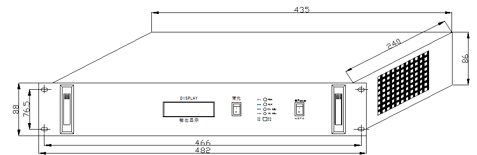
Dimension |
482*240*88mm |
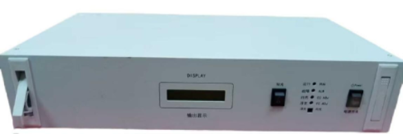
Panel introduce

|
Number |
Name |
Description |
|
Front panel |
||
|
1 |
Install hole |
|
|
2 |
Invisible handle |
|
|
3 |
LCD display Window |
Display the voltage and current |
|
4 |
Backlight |
Switch ON/OFF for the LCD Display window light |
|
5 |
RUN |
DC-DC Converter with output , The run indicator ON in green color DC-DC Converter without output, The run indicator OFF |
|
6 |
ALM |
DC-DC Converter fault or under protection , ALM Indicator ON in Red color DC-DC Converter work in normal , the ALM indicator OFF |
|
7 |
EC ADJ/FC ADJ |
Equal voltage / Float voltage adjustable knob |
|
8 |
FC /EC MANU /AUTO
|
Dial code for Float /Equal Charge and Manual/automatic A==Switch Float charge and Equal charge. Turn to right is Equal charge , Turn to left is float charge B== Switch Manual and automatic. Turn to right is automatic , Turn to left is Manual This function only work under ac-dc switching mode power supply Noted : This function work for AC TO DC Mode only |
|
9 |
Power |
Switch ON/OFF of the dc converter |
|
Rear panel |
||
|
1 |
DC Voltage input terminal |
(﹢)、(﹣)24Vdc |
|
2 |
PE SH SH (+)(-) Current sharing |
Parallel connect port Use several units of the same specification of converter connect together to get max current output For ac to dc power supply with battery interface function , this port did not connect and work |
|
3 |
DC Voltage Output terminal |
2 channel (﹢)、(﹣) &(﹢)、(﹣) Each channel support max 25A For example , it can work CH1-0A&CH2-25A; CH1-10A&CH2-15A; CH1-12A&CH2-13A; CH1-15A&CH2-10A; CH1-20A&CH2-5A; and so on |
|
4 |
GND |
|
Part 7. Installation and commissioning
A. Installation environment requirements
The equipment must be work in No conductive dust explosion, non-corrosive gDSes and vapors environment.
Installation environment must to be far away from heat and electromagnetic interference
In addition, it must be leaving adequate enough space to facilitate heat dissipation, cooling air holes and block
1. Environment temperature:-5℃~45℃
2. Environment Humidity:10%~90%RH
3. The power system must be stable place and no severe shock during Installing.
B. Checking Boxing
After receive the parcel, pleDSe open it then check whether all the accessories are complete or not. If there are any problems, pleDSe contact with us immediately.
C. Install
Booting and Shut OFF
1. Closed the AC/DC input switching after power module connect the AC/DC input then the power module(Converter) into the working state
2. The RUN LED will on then will have DC Output voltage
3. The power converter will be stop working after cut off AC input and RUN LED Off then the power converter without output
Function key operating
1. FC /EC DIAL : Used to switch float charge and equal charge
2. MANU /AUTO: Used to switch MANUAL charge and AUTO MATIC charge
Noted: Automatic float equal charge must be compatible with the power monitoring system)
Indicator light
1. RUN LED ON (Green) means the power converter work normally with output
2. ALM LED ON (Red) means the power converter is failed or power converter module in a state of self-protection.
DC Output setting
Under normal circumstances, the DC output power module factory set at the following values
1. Float voltage:121.5±0.25V VFL。
2. Equal Voltage:130.5±0.25V VEQ
3. Output Current limited: 101%-105% ILIM
If users need to change the factory setting, according to the following methods to re-set
Setting float voltage
In Floating state, adjust “FC ADJ” potentiometer on the front panel then you can re-set the float voltage.
(Note: The output voltage is higher than 60V, the module will protect and shutdown.)
Setting equal voltage
In equal state, adjust “EC ADJ” potentiometer on the front panel then you can re-set the equal voltage.
Equal voltage will be adjust and change at the same time when the float adjust and it need to re-adjust
Set the output voltage should ensure that the output did not enter the current-limiting step-down process, otherwise the actual output voltage will be far more than the required voltage and may cause over-voltage protection shutdown. Can be adjusted in a single module or system no-load cDSe
l Voltage current display calibration
The voltage and current calibration need to be carried out inside the module, RV3 (VDJ) voltage display calibration potentiometer, RV2 (CDJ) for the current display calibration potentiometer.
The power converter Module had be calibrated at the factory